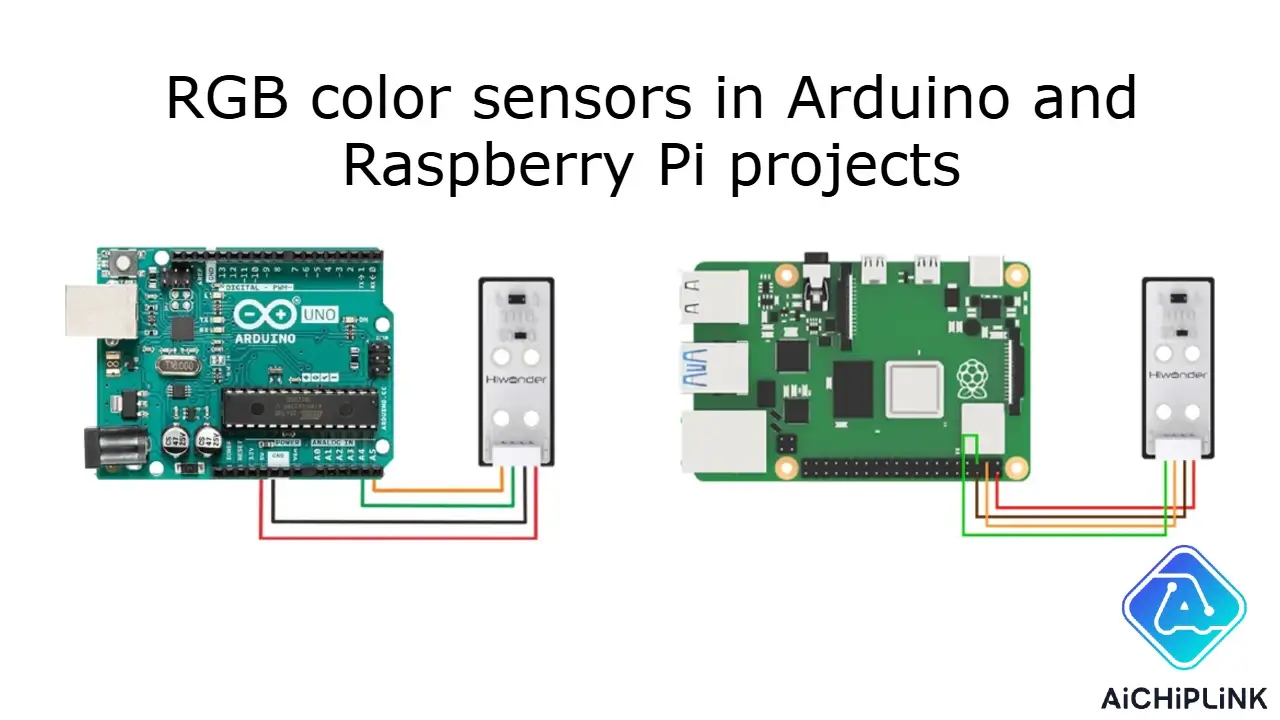
If you want to add colors to your arduino or raspberry pi project, rgb color sensors help a lot. You connect the sensor, upload some code, do a quick calibration, and then you can read colors. The tcs3200 color sensor gives a frequency output. The tcs34725 sensor uses i2c to give digital data. Both sensors let you measure rgb values in arduino projects. Here’s a quick look:
| Sensor Model | Key Features | Output Type |
|---|---|---|
| tcs3200 | Programmable gain, frequency output, handles variable lighting | Frequency signal |
| tcs34725 | High accuracy, infrared filter, on-chip LED | Digital (i2c) |
You do not need special skills. Just follow each tutorial step and your setup will detect color like an expert!
Key Takeaways
-
RGB color sensors like TCS3200 and TCS34725 help your Arduino or Raspberry Pi projects find colors easily.
-
TCS3200 gives out frequency signals. TCS34725 sends digital data using I2C. This makes it easier and more correct.
-
Good wiring and setting up under the same light are important for correct color readings.
-
Use sample code and libraries to read sensor data. You can also control RGB LEDs to show what you find.
-
Try projects like sorting colors or making displays you can use. This helps you learn and make fun, helpful things.
RGB Color Sensors
How They Work
Have you ever wondered how rgb color sensors see color? These sensors have tiny photodiodes. Each photodiode has a filter for red, green, or blue light. When light shines on something, the sensor checks how much of each color comes back. The tcs3200 color sensor has a grid of photodiodes. It can switch between red, green, and blue filters using its pins. The sensor changes the light it sees into a square wave signal. If the wave is faster, the color is stronger. You can count these waves to find the rgb values. The tcs34725 works almost the same way. But it sends digital data right to your microcontroller.
-
Photodiodes with filters let only one color pass at a time.
-
The sensor turns light into a signal you can measure.
-
You can switch filters to test each color by itself.
-
The tcs3200 uses a frequency signal, but the tcs34725 uses digital data.
Types and Features
There are many kinds of color sensors. Some are simple and good for hobby projects. Others are made for factories. Here are some popular models:
| Sensor Type / Model | Application Area | Key Specifications & Features |
|---|---|---|
| tcs3200 | Hobby, DIY, education | Frequency output, adjustable gain, low cost |
| tcs34725 | Hobby, DIY, education | I2C interface, high sensitivity, built-in IR filter |
| SA1J Series | Industrial color recognition | Fast response, reliable in tough environments |
| COLORMAX Series | Color and luminosity detection | Wide range, USB/RS232, high intensity LED |
| LEX-1000 | Industrial, automation | Four programmable channels, analog and digital outputs |
The tcs3200 is liked because it is cheap and simple. The tcs34725 is more accurate and works even behind dark glass. Some sensors, like the LEX-1000, have special features for factories. These include programmable channels and strong cases.
Output Signals
You need to know how your color sensor sends data to Arduino or Raspberry Pi. The tcs3200 sends a square wave signal. The wave’s speed matches the color strength. You count how many times the wave goes up and down in a set time. The tcs34725 sends digital rgb color data over I2C. Your microcontroller reads these numbers right away.
| Feature/Aspect | tcs3200 Color Sensor | tcs34725 Sensor |
|---|---|---|
| Output Signal Type | Square wave (frequency) | Digital color data (16-bit values) |
| Interface | Frequency output (OUT pin) | I2C digital communication |
| How Microcontroller Reads Data | Counts pulses to measure color intensity | Reads digital values for red, green, blue, clear |
| Extra Features | Adjustable gain, frequency scaling | Programmable gain, integration time, IR filter |
Tip: If you want fast and easy color detection, try the tcs3200 color sensor. If you need better accuracy, the tcs34725 is a good pick.
Components and Wiring
Getting your color sensor working with Arduino or Raspberry Pi starts with the right wiring. You need to connect each sensor pin to the correct spot on your board. Let’s walk through the steps for both TCS3200 and TCS34725 sensors. I’ll also show you how to hook up an RGB LED for color feedback.
Arduino Wiring
You can use either the TCS3200 or TCS34725 color sensor with your Arduino. Each sensor has its own wiring method. The TCS3200 uses a frequency output, while the TCS34725 uses I2C communication. Here’s how you wire them:
TCS3200 Pinout and Wiring
The TCS3200 color sensor has several pins. You connect them to your Arduino like this:
| TCS3200 Pin | Arduino Pin | Function |
|---|---|---|
| VCC | 5V | Power supply |
| GND | GND | Ground |
| OUT | Digital pin (e.g. 2) | Frequency output |
| S0, S1 | Digital pins (e.g. 3, 4) | Frequency scaling |
| S2, S3 | Digital pins (e.g. 5, 6) | Color filter select |
| OE | GND (enable output) | Output enable |
-
Connect VCC to the 5V pin on your Arduino.
-
Connect GND to any ground pin.
-
OUT goes to a digital pin, like pin 2.
-
S0 and S1 control the frequency scaling. You can use pins 3 and 4.
-
S2 and S3 select which color filter is active. Use pins 5 and 6.
-
OE (output enable) should go to ground to keep the sensor active.
TCS34725 Pinout and Wiring
The TCS34725 color sensor uses I2C, which makes wiring simple. Here’s a quick table:
| TCS34725 Sensor Pin | Arduino Pin Connection |
|---|---|
| LED | Any digital pin |
| SDA | A4 (I2C Data) |
| SCL | A5 (I2C Clock) |
| 3.3 V | 3.3V |
| GND | GND |
Follow these steps for your setup:
-
Connect the GND pin of the TCS34725 sensor to any GND pin on the Arduino.
-
Connect the SDA pin to Arduino pin A4.
-
Connect the SCL pin to Arduino pin A5.
-
Connect the VIN or VCC pin to the 5V pin on the Arduino.
-
If you want to control the onboard LED, connect the LED pin to a digital pin.
Tip: Always double-check your wiring before powering up your Arduino. Using the wrong voltage can damage your color sensor.
Raspberry Pi Wiring
You can also use the TCS3200 or TCS34725 color sensor with a Raspberry Pi. The TCS34725 is especially easy because it uses I2C. Here’s how you wire it:
TCS34725 Pinout for Raspberry Pi
| Pin Name | Function / Connection | Notes |
|---|---|---|
| VIN | Power supply input | Connect to 3.3V |
| GND | Ground | Connect to Pi ground |
| SDA | I2C Data line | Connect to GPIO2 (SDA) |
| SCL | I2C Clock line | Connect to GPIO3 (SCL) |
| LED | Onboard white LED control | Can be connected to GND to disable LED |
| INT | Interrupt output (optional) | Connect to any GPIO if needed |
Here’s a step-by-step guide:
-
Connect VDD to the 3.3V power supply on the Raspberry Pi.
-
Connect GND to the Pi ground.
-
Connect SCL and SDA to the Pi’s I2C clock (GPIO3) and data (GPIO2) pins.
-
If you want to use interrupts, connect the INT pin to a Pi GPIO pin.
-
You can leave the OE pin unconnected or connect it to ground.
-
For extra lighting, connect an external LED to the LED pin.
Note: Use pull-up resistors on the I2C lines if your Pi doesn’t have them already. This helps keep your color sensor communication stable.
TCS3200 with Raspberry Pi
The TCS3200 color sensor can work with a Raspberry Pi, but it’s a bit trickier. The Pi reads the frequency output from the OUT pin. You connect the sensor’s VCC to 5V, GND to ground, and OUT to a GPIO pin. S0, S1, S2, and S3 go to other GPIO pins for control. Make sure you use level shifters if your Pi only supports 3.3V logic.
Safety Tip: Never power your sensor with more voltage than it can handle. Always use a stable power supply and avoid short circuits.
RGB LED Connections
Adding an RGB LED to your setup lets you show the color your sensor detects. You connect the LED’s red, green, and blue legs to Arduino PWM pins. Here’s a common setup:
| RGB LED Pin | Arduino Pin | Resistor Value |
|---|---|---|
| Red | 3 | 220Ω |
| Green | 5 | 470Ω |
| Blue | 6 | 220Ω |
-
Use current-limiting resistors to protect your LED. Some modules have these built in.
-
Connect the common cathode (longest leg) to ground.
Pro Tip: Start with a breadboard for testing. This makes it easy to fix mistakes before soldering.
Frequency Output vs. I2C Communication
The TCS3200 color sensor sends a frequency output. Your Arduino counts the pulses to measure color intensity. The TCS34725 uses I2C, so your Arduino or Pi reads digital color data directly. I2C is easier for beginners and gives more accurate results.
The Role of the IR Filter
The TCS34725 color sensor has a built-in IR filter. This filter blocks infrared light, which can mess up your color readings. Without an IR filter, your sensor might see colors as washed out or tinted. The filter helps your sensor detect only visible light, so you get true-to-life colors.
Tools and Materials
Here’s a handy table of what you need for your color sensor setup:
| Component/Tool | Purpose/Use |
|---|---|
| Arduino board | Controls the color sensor and LED |
| TCS3200 or TCS34725 sensor | Detects color |
| RGB LED | Shows detected color |
| Resistors (220Ω, 470Ω) | Protects the LED |
| Breadboard & jumpers | For easy circuit building |
| Soldering iron | For permanent connections |
| Raspberry Pi | Alternative to Arduino for more advanced projects |
| PC | For programming your Arduino or Pi |
Remember: Always use safe voltage levels and trusted power supplies. If you’re not sure about wiring, ask for help from someone with electronics experience.
Programming and Reading Colors
Now your color sensor is wired. Next, you need to add code. The code lets you read data from the sensor. You can also use an RGB LED to show colors. Let’s see how to do this with Arduino and Raspberry Pi.
Arduino Code
Arduino can read both TCS3200 and TCS34725 sensors. Each sensor needs its own code. But both are easy to use with examples.
The Adafruit_TCS34725 library is the best choice for the TCS34725 sensor. You can get it from the Arduino IDE Library Manager. This library helps you start the sensor and read RGB data. It also has example code to help you learn.
For the TCS34725, you need two libraries: Wire.h for I2C and Adafruit_TCS34725.h for the sensor. Here is some sample code:
#include <Wire.h>
#include "Adafruit_TCS34725.h"

Adafruit_TCS34725 tcs = Adafruit_TCS34725();

void setup() {
  Serial.begin(9600);
  if (tcs.begin()) {
    Serial.println("Color sensor found!");
  } else {
    Serial.println("No TCS34725 found ... check your wiring?");
    while (1);
  }
}

void loop() {
  uint16_t r, g, b, c;
  tcs.getRawData(&r, &g, &b, &c);

  Serial.print("R: "); Serial.print(r);
  Serial.print(" G: "); Serial.print(g);
  Serial.print(" B: "); Serial.print(b);
  Serial.print(" C: "); Serial.println(c);

  delay(500);
}
This code gets red, green, blue, and clear values from the sensor. You can see the numbers in the Serial Monitor. You can use these numbers to find colors or control an RGB LED.
The TCS3200 code is a bit different. You use digital pins to control the sensor and measure frequency. Here is a simple example:
#define S0 3
#define S1 4
#define S2 5
#define S3 6
#define sensorOut 2

void setup() {
  pinMode(S0, OUTPUT);
  pinMode(S1, OUTPUT);
  pinMode(S2, OUTPUT);
  pinMode(S3, OUTPUT);
  pinMode(sensorOut, INPUT);

  digitalWrite(S0, HIGH);
  digitalWrite(S1, LOW);

  Serial.begin(9600);
}

void loop() {
  // Red
  digitalWrite(S2, LOW);
  digitalWrite(S3, LOW);
  int redFrequency = pulseIn(sensorOut, LOW);

  // Green
  digitalWrite(S2, HIGH);
  digitalWrite(S3, HIGH);
  int greenFrequency = pulseIn(sensorOut, LOW);

  // Blue
  digitalWrite(S2, LOW);
  digitalWrite(S3, HIGH);
  int blueFrequency = pulseIn(sensorOut, LOW);

  Serial.print("R: "); Serial.print(redFrequency);
  Serial.print(" G: "); Serial.print(greenFrequency);
  Serial.print(" B: "); Serial.println(blueFrequency);

  delay(500);
}
You can use these numbers to find colors by comparing the values. Lower frequency means the color is stronger.
Many people think the Adafruit_TCS34725 library is easier and works better than TCS3200 libraries. If you want less trouble, use TCS34725 with the Adafruit library.
Raspberry Pi Code
If you use a Raspberry Pi, you will write code in Python. The TCS34725 sensor works well with the Pi because it uses I2C. You can use a Python library to read color data.
Most guides use Python to read the sensor and show colors. Here is a sample code to help you start:
import board
import busio
import adafruit_tcs34725

i2c = busio.I2C(board.SCL, board.SDA)
sensor = adafruit_tcs34725.TCS34725(i2c)

while True:
    r, g, b, c = sensor.color_raw
    print("R: {} G: {} B: {} C: {}".format(r, g, b, c))
This code prints the red, green, blue, and clear values from your sensor. You can use these numbers to find colors or control other things.
If you use the TCS3200 with Raspberry Pi, you must read the frequency using GPIO pins. You can use RPi.GPIO or gpiozero to read the pulses. Most people like the TCS34725 better with the Pi because I2C is easier.
Here is a table that shows the main differences between Arduino and Raspberry Pi code for reading color sensor data:
| Aspect | Arduino Code Structure | Raspberry Pi Code Structure |
|---|---|---|
| Programming Language | C++ (Arduino Sketch) | Python |
| Code Structure | Uses setup() and loop() functions | Procedural, no fixed setup/loop |
| GPIO Handling | pinMode(), digitalWrite(), pulseIn() | RPi.GPIO or gpiozero libraries |
| Sensor Reading Method | pulseIn() or library functions | Library functions (e.g., adafruit_tcs34725) |
| Calibration and Mapping | map() function | Custom mapping or library functions |
| Output | Serial Monitor | Console or GUI |
| Hardware Interaction Level | Low-level, microcontroller-centric | Higher-level, runs on Linux OS |
You can see Arduino code uses setup and loop. Raspberry Pi code is a script that runs from top to bottom.
Data Interpretation
Reading numbers from your sensor is just the start. You need to turn these numbers into real colors. The sensor gives you red, green, and blue values. These numbers may not match what you see, so you must process them.
Here are some tips for using color sensor data:
-
Take several readings and use the average. This helps make your results more stable.
-
Change your raw data to the 0-255 RGB range. Set low values to 0 and high values to 255. Use math to fit the numbers in between.
-
You can change RGB data to HSL or HSV. This helps match what people see.
-
Calibrate your sensor with the same light you will use. Different lights can change your results a lot.
-
Use filters or smoothing to reduce noise. Kalman filters work well for frequency sensors.
-
For very accurate color detection, you can use machine learning to guess colors from your data.
Raw RGB sensor data does not always match what people see. You need to change your sensor’s output to standard color spaces like sRGB or Adobe RGB. Calibration is very important, especially if your lighting is not perfect. Sometimes, the sensor sees two colors as different even if they look the same to you. Always calibrate and use math to get the best color readings.
When you process your data, it is easier to find colors like red, green, or blue. You can use your code to check if the numbers match known color ranges. For example, if red is much higher than green and blue, you are probably seeing a red object.
If you want to show the color, you can use your code to light up an RGB LED. This gives you quick feedback and makes your project fun.
With these tips, you will get the best results from your color sensor and code. You will detect colors well and make your Arduino or Raspberry Pi project special!
Color Sensor Calibration and Troubleshooting
Calibration Steps
Getting your colors right starts with a good calibration process. You want your project to see colors the same way you do. For the TCS3200, you can follow these steps:
-
Place a black card in front of the sensor. Record the frequency reading. This is your dark frequency. It shows what the sensor sees with no light.
-
Next, use a white card. Record the frequency again. This is your white frequency. It shows the sensor’s response to pure white.
-
Use these two numbers to set up a linear equation. This lets you map any reading to a value between 0 and 255 for each color.
-
Repeat this for red, green, and blue. Now, your sensor can turn any reading into real RGB colors.
The TCS34725 works a bit differently. It sends digital data, but you still need to check your readings with black and white cards. This helps you adjust your code for the most accurate colors.
Tip: Always calibrate under the same lighting you plan to use in your project. Light changes can shift your colors a lot.
Common Issues
You might run into problems when you try to read colors. Here are some things to watch out for:
-
Ambient light can mess up your readings. Try to block outside light from hitting your sensor.
-
If your LED shines straight into the sensor, you get noisy colors. Use a cover or tube to keep the light focused on your sample.
-
Sometimes, the readings jump around. This can happen if your power supply is not stable or if you have wires too close together.
-
Different RGB LEDs can show slightly different colors, even if they look the same. This makes calibration tricky.
-
If your colors look off, check your wiring and make sure you use the right code for your sensor model.
A small capacitor between the AREF pin and ground can help smooth out noisy readings. Some people use two boards—one for the sensor and one for the LEDs—to keep things stable.
Tips for Accurate Colors
You want your project to show true colors every time. Here are some tips:
-
Keep your sensor and sample at the same distance for each test. Changes in distance can change the colors you see.
-
Use a lens or a pinhole to block out extra light. This helps your sensor focus on the right colors.
-
Clean your sensor often. Dust and dirt can change the way it sees colors.
-
Watch out for temperature changes. Hot or cold rooms can make your colors drift. Calibrate again if the temperature changes a lot.
-
Try using an ambient light sensor with your color sensor. This lets you adjust for changes in room lighting.
-
Use example code from trusted sources. Good code helps you get the best colors.
-
If you use the TCS34725, its IR filter helps block out unwanted light, making your colors more accurate.
Remember: Regular calibration keeps your colors sharp and true. If your colors start to look strange, check your setup and recalibrate.
Project Ideas
Color Sorting Project
You can build a fun color sorting project with your RGB color sensor. Many people use the TCS34725 sensor for this because it gives you fast and accurate results. In fact, this sensor can sort colors with over 95% accuracy, even when you test thousands of samples. If you want to make a color sorting machine, you just need to connect the sensor to your arduino and set up a small conveyor or chute. The sensor checks each object’s color and then tells a motor or servo to move it to the right bin. This type of project is popular in color recognition projects and helps you learn about sensors, motors, and programming. The TCS3200 sensor also works for color sorting, but it can struggle with dark colors or tricky lighting. You might see lower accuracy, so make sure you calibrate carefully.
Tip: Always test your project under the same lighting you plan to use. This keeps your color sorting results steady.
Interactive Color Display
Want to see colors come to life? Try an interactive color display project. You can use your arduino and a TCS3200 or TCS34725 sensor to read the color of any object. Then, show that color on an RGB LED or even an LCD screen. Here’s how you can do it:
-
Connect your sensor to the arduino.
-
Write code to read the color data.
-
Use the RGB values to light up an LED or display the color on a screen.
This project helps you understand how sensors turn real-world colors into numbers. You can even use the serial monitor to watch the color values change as you move different objects in front of the sensor. Many arduino projects use this idea to teach about color and light.
| Sensor Model | Display Method | Best Use Case |
|---|---|---|
| TCS3200 | RGB LED, LCD | Quick color feedback |
| TCS34725 | LCD, GUI on Pi | High-accuracy display |
Arduino and Raspberry Pi Integration
You can make your project even smarter by combining arduino and Raspberry Pi. For example, use the arduino to read the sensor’s frequency output and send the data to the Pi for more advanced processing. This setup works well for projects that need both real-time color detection and complex actions, like sorting or logging data. The TCS3200 sensor needs you to read each color one at a time, but you can solve this by using extra chips or clever code. The Pi can’t read frequency signals directly, so you might add a counter chip to help. When you put both boards together, you get the best of both worlds: fast sensor reading from arduino and smart control from Raspberry Pi. This combo is great for big color sorting projects or when you want to connect your project to the internet.
Note: Always calibrate your project and check your wiring. This helps your color sorting and display projects work every time.
You can bring your ideas to life with RGB color sensors and a bit of creativity. Here’s what helps you succeed:
-
Connect your sensor and check your wiring.
-
Write code to read colors and control LEDs.
-
Calibrate for the best results.
-
Try a project like smart lighting or interactive art.
-
Use high-quality parts and join online communities for support.
If you want to go further, explore GitHub color science libraries or read guides on color mapping and sensor calibration. The Random Nerd Tutorials site has a great step-by-step guide for the TCS3200 sensor with Arduino. Your next project could inspire others!
FAQ
How do I know if my color sensor is working?
You can check your sensor by running the example code. If you see changing numbers in the Serial Monitor or terminal when you move colored objects in front of the sensor, it works!
Can I use both TCS3200 and TCS34725 with Raspberry Pi?
You can use both, but the TCS34725 is much easier. It uses I2C, which the Pi supports well. The TCS3200 needs extra steps because it sends a frequency signal.
Why do my color readings change in different rooms?
Light changes everything! Different bulbs or sunlight can affect your sensor. Always calibrate your sensor in the same lighting where you plan to use it.
What should I do if my sensor gives wrong colors?
First, check your wiring and code. Clean the sensor lens. Try calibrating again. If you still see problems, block extra light or use a tube to focus on your sample.
Can I use more than one color sensor in my project?
Yes! You can connect multiple sensors. Just make sure each sensor has a unique address if you use I2C. For TCS3200, use different pins for each sensor’s output.

Written by Jack Elliott from AIChipLink.
AIChipLink, one of the fastest-growing global independent electronic components distributors in the world, offers millions of products from thousands of manufacturers, and many of our in-stock parts is available to ship same day.
We mainly source and distribute integrated circuit (IC) products of brands such as Broadcom, Microchip, Texas Instruments, Infineon, NXP, Analog Devices, Qualcomm, Intel, etc., which are widely used in communication & network, telecom, industrial control, new energy and automotive electronics.
Empowered by AI, Linked to the Future. Get started on AIChipLink.com and submit your RFQ online today!